
Choosing the right Stocko Connector in 2026 requires more than matching pins and housing shapes. Engineers must examine current ratings, wire sizes, pitch, temperature limits, vibration resistance, and locking performance. A connector may fit perfectly on a drawing yet fail beside a hot motor or vibrating control panel.
Ron Bishop, founder of Bishop & Associates, has emphasized this practical principle: “A connector must be selected for the application, not merely for its appearance.” That advice remains valuable when comparing Stocko Connector solutions for appliances, automotive systems, industrial controls, and compact electronic assemblies. The best choice begins with real operating conditions, not catalog convenience.
Small details matter. A 2.8-millimeter terminal can behave differently after repeated crimping. Plating quality can influence contact stability over time. Housing material can affect heat resistance, stiffness, and assembly confidence. Designers should verify the manufacturer’s datasheet, application limits, test evidence, and traceability records. They should also test the connector with the actual wire, tool, and enclosure.
That sounds obvious. It is often missed.
A careful selection process should compare service life, installation speed, field replacement needs, and total cost. The cheapest part may create expensive rework later. However, premium specifications are not automatically better. Some projects overdesign the connection and waste valuable space or budget. This guide examines those trade-offs honestly, including the uncomfortable gaps between laboratory ratings and everyday use. The goal is a reliable Stocko Connector choice that survives real assembly conditions, not just a convincing product description.
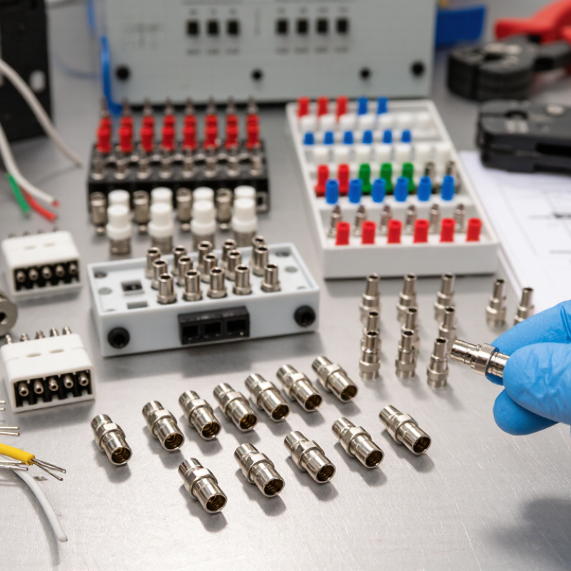
A Stocko connector is a compact electrical connector that joins wires, terminals, or small circuit boards. Many versions use crimping, spring pressure, or insulation-displacement contact. They are common in appliances, lighting assemblies, control panels, heating equipment, and automotive subassemblies. Their small size helps engineers save space behind a switch or inside a narrow housing. The connection may look simple. It still carries real safety responsibilities.
Fortune Business Insights valued the global connector market at USD 84.84 billion in 2023. Its report forecasts USD 146.31 billion by 2032. Grand View Research also identifies miniaturization and rising electronics content as major growth drivers. These figures explain why compact connectors matter in 2026. However, market growth does not make every connector suitable. Check current rating, wire size, contact material, temperature range, and vibration resistance. A connector for a quiet control panel may fail inside a vibrating vehicle.
Look closely at the installation. Is the wire solid or stranded? Will workers assemble it by hand or with tooling? Does moisture reach the housing? IEC 60512 test methods can help verify electrical and mechanical performance. A practical check includes pulling the wire gently, measuring contact resistance, and inspecting the terminal under magnification. Do not rely on appearance alone. That shortcut is tempting, but often wrong. In real projects, connector selection is sometimes rushed, and the cable specification gets overlooked. That mistake deserves another review.
Choosing the right connector requires more than matching a catalog photograph. Compare pitch, contact count, wire size, rated current, and voltage first. A 2.5 mm pitch may fit a compact board, but it can limit insulation clearance. Check the actual conductor diameter, not only the stated cable gauge.
Current capacity needs careful interpretation. A 2024 MarketsandMarkets report valued the global connector market at roughly 84 billion US dollars and forecast continued growth through 2029. That growth reflects higher density and harsher operating conditions. Compare current ratings at the real ambient temperature. A connector rated at 10 amperes may carry less when several adjacent circuits heat the housing. Derating tables matter.
Review contact resistance, insulation resistance, temperature range, mating cycles, and retention force. IEC 60512 test methods help make supplier claims comparable. For dusty or wet equipment, examine the required protection rating and sealing design. For enclosed machinery, check flammability performance and material traceability. Industry surveys repeatedly identify reliability and lifecycle cost as major purchasing factors, yet buyers still overvalue the lowest unit price. That is a mistake, sometimes mine too.
During evaluation, measure voltage drop across a mated pair after thermal cycling. Inspect terminals under magnification. A connector can pass an initial test and still loosen after vibration. Keep a small margin above the calculated load; real assemblies rarely remain perfectly clean, cool, or stationary. Specification sheets can be incomplete, so request test conditions, sample size, and revision-controlled drawings before approval.
Choosing a connector starts with the application, not the catalog. Define the circuit’s voltage, current, wire size, and available space. A compact housing may look efficient, but tight terminals can complicate assembly and maintenance. Measure twice. Consider the operating temperature, humidity, dust, and chemical exposure around the equipment. A connector used near a motor may also need strong vibration resistance and a dependable locking feature.
Contact material and plating affect performance over time. Select terminals that suit the expected current and switching frequency. For outdoor equipment, sealing and corrosion resistance deserve careful attention. For control panels, clear polarization can prevent incorrect mating during installation. Check the required insertion cycles, too. A connector for occasional service does not need the same durability as one handled every day.
In field projects, I have seen small oversights create large delays. Engineers sometimes choose a connector by pitch alone, then discover that the cable bends beyond its safe radius. Another common mistake is ignoring heat from nearby components. It is worth testing a sample under real load, vibration, and temperature conditions. Specifications guide the decision, but hands-on validation reveals weaknesses. No selection is perfect. Leave room to reconsider the design before production begins.
Compatibility begins with the application, not the catalogue photo. Check pitch, pole count, wire gauge, current rating, voltage rating, and mating direction. Confirm the housing accepts your exact terminal size. A connector may fit physically but fail electrically. Measure the cable jacket and insulation diameter too. Small differences can weaken strain relief.
Safety needs evidence. NFPA’s Home Structure Fires report found electrical distribution and lighting equipment involved in 12% of reported home structure fires from 2016–2020. Use connectors with documented temperature, flame, and insulation performance. Compare the product data with IEC 61984 and IEC 60512 test requirements. Derating matters. Heat, vibration, moisture, and continuous current can reduce the practical rating.
Installation conditions are often underestimated. Inspect crimp height, terminal retention, locking force, and exposed copper. IPC/WHMA-A-620 provides useful workmanship criteria for wire and cable assemblies. Leave enough service length for a clean bend. Do not force a misaligned latch. I have seen a connector pass a bench test, then loosen after repeated vibration. That mistake is easy to repeat. A final pull test, polarity check, and continuity test should be recorded before production release. Clearance around the housing also matters. It is rarely checked early enough.
Selecting the best connector for 2026 projects begins with the equipment, not a catalogue image. Define circuit current, working voltage, wire size, contact pitch, and available panel space. Then check the real environment: heat, moisture, dust, vibration, and repeated mating. A connector that fits on the bench may loosen beside a motor. Measure twice. Use the highest expected load, not the average reading, and leave a practical safety margin.
Review the terminal material, plating, housing temperature rating, and retention method. Spring terminals can support fast assembly, while locking features help resist vibration. For field service, clear polarity marks and tool access matter as much as electrical performance. Ask for test data, dimensional drawings, and traceable quality records. Independent verification is valuable when the application faces heat or mechanical stress. “Meets standard” is not enough without the standard number and test conditions.
For 2026 projects, assess supply stability and replacement options early. Confirm lead times, minimum order quantities, approved alternatives, and documentation before freezing the design. Prototype the connector in a loaded assembly, then inspect heating, pullout force, and contact stability after cycling. Do not trust one perfect sample. Real production can expose weak crimps, inconsistent wire preparation, or cramped access. I would also revisit the choice after installation; hindsight often reveals a safer improvement.
Use this engineering selection guide to compare connector configurations against electrical, mechanical, environmental, and installation requirements.
| Project Requirement | Recommended Connector Configuration | Typical Electrical Range | Key Mechanical Considerations | Environmental Considerations | Best-Fit Applications |
|---|---|---|---|---|---|
| Compact Design Limited PCB or harness space | Low-profile wire-to-board or wire-to-wire connector with a small pitch | Approximately 1–5 A per contact and up to 250 V AC/DC, depending on contact size and spacing | Check creepage, clearance, terminal retention, mating direction, and cable-exit space | Suitable for controlled indoor equipment when the connector is protected from dust, moisture, and excessive vibration | LED modules, compact controls, display assemblies, small appliances, and space-constrained electronics |
| Higher Current Power distribution or motor-related loads | Larger terminal system with wider contacts, positive retention, and adequate conductor cross-section | Common low-voltage power designs range from approximately 5–20 A per contact; final current depends on temperature rise and conductor size | Evaluate contact resistance, derating, terminal crimp quality, mating force, and resistance to cable pullout | Allow for heat dissipation and avoid sealed or enclosed layouts that can increase operating temperature | Power supplies, industrial controls, appliance wiring, lighting equipment, and low-voltage distribution |
| Fine-Pitch Signal Dense signal wiring | Multi-position connector with closely spaced contacts and polarization features | Typically used for low-current signals, often below 1 A per contact; voltage rating must be checked against spacing and insulation requirements | Prioritize terminal alignment, contact normal force, insertion accuracy, and protection against mis-mating | Use additional protection where dust, condensation, or corrosive gases could affect low-level signals | Sensors, control panels, instrumentation, displays, communication interfaces, and internal device wiring |
| Vibration Exposure Equipment subject to movement or shock | Locking connector with positive latching, secure terminal retention, and strain relief | Electrical ratings remain application-dependent; vibration can increase contact resistance if retention is inadequate | Select a visible latch, secondary lock where available, cable support, and terminals rated for the expected vibration profile | Confirm vibration, mechanical shock, and temperature test requirements using the applicable equipment standard | Industrial machinery, transportation equipment, HVAC systems, automation cabinets, and mobile equipment |
| Frequent Servicing Repeated connection and disconnection | Releasable connector with guided mating, clear polarization, and a robust locking mechanism | Select a current and voltage rating that remains valid after the expected number of mating cycles | Verify mating-cycle rating, contact plating, insertion force, extraction force, and accessibility for technicians | Consider wear, contamination, and the need for protective caps or covers during service intervals | Test equipment, replaceable modules, serviceable appliances, battery interfaces, and production fixtures |
| Harsh Environment Moisture, dust, or temperature variation | Connector system with a suitable sealing concept, protected contacts, and mechanically secure locking | Apply voltage and current derating when temperature, moisture, contamination, or reduced insulation resistance is expected | Check sealing geometry, cable diameter range, strain relief, locking security, and resistance to corrosion | Confirm the required IP protection level, operating temperature, humidity, chemical exposure, and UV resistance | Outdoor controls, industrial sensors, agricultural equipment, HVAC units, and equipment installed in dusty areas |
| Automated Assembly High-volume production | Connector designed for consistent crimping, repeatable insertion, and automated or semi-automated handling | Use the manufacturer’s validated terminal range and conductor-size limits to maintain stable electrical performance | Evaluate crimp tooling, pull-force results, terminal orientation, housing feeding, poka-yoke features, and inspection access | Confirm material compatibility with the production process, including soldering, cleaning, and assembly temperatures | Appliances, lighting production, industrial electronics, control systems, and high-volume cable harnesses |
| Safety-Critical Wiring Equipment requiring controlled failure risk | Polarized, positively locking connector with clear circuit identification and documented assembly controls | Select ratings with appropriate continuous-load, temperature, insulation, and fault-condition margins | Require secure terminal retention, secondary locking where applicable, clear keying, and verified crimp performance | Review applicable product standards, flammability requirements, temperature limits, and environmental qualification | Safety controls, medical equipment subassemblies, industrial protection systems, and regulated electronic products |
| Wire Harness Optimization Reliable and efficient cable assembly | Connector selected together with the terminal, wire gauge, insulation diameter, seals, and strain-relief accessories | Match the conductor cross-section to the approved terminal range; account for bundling and ambient-temperature derating | Verify wire-strip length, crimp height, crimp width, pull-out force, bend radius, and harness routing | Choose materials and sealing components compatible with heat, oil, chemicals, humidity, and expected service life | Custom cable assemblies, control cabinets, appliances, lighting harnesses, and machine wiring |