What Are Pneumatic Valves and How Do They Work?
Pneumatic Valves control compressed air in systems that power cylinders, grippers, clamps, and other industrial equipment. They act like traffic controllers, sending air toward one actuator port while releasing pressure from another. In a packaging line, for example, a valve may extend a cylinder to push a carton, then reverse airflow to retract it. The process looks simple. It is not always simple.
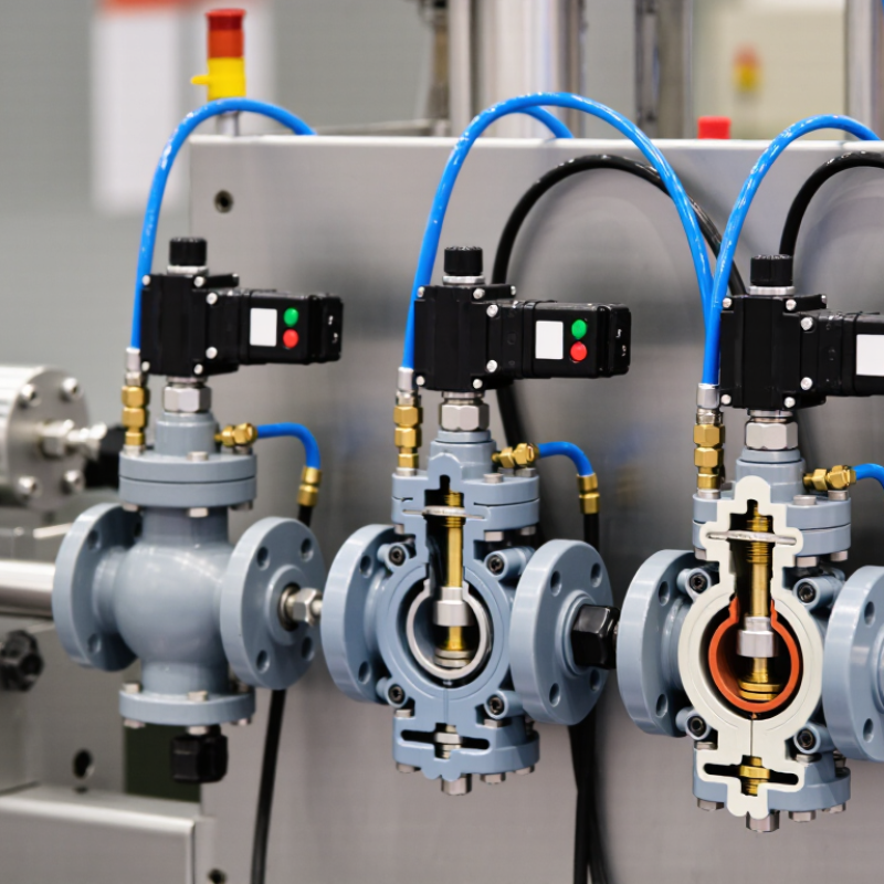
A pneumatic valve typically includes a body, spool or poppet, seals, ports, and an actuator. An electrical solenoid, mechanical lever, or pilot signal moves the internal element. That movement changes the airflow path. A three-way valve can supply, exhaust, or block air. A four-way valve can control both sides of a double-acting cylinder. Pressure, flow rate, response time, and port size affect the final motion. A small restriction can make a cylinder hesitate.
Reliable valve selection requires more than matching thread size. Engineers should check operating pressure, air quality, temperature, duty cycle, voltage, and required safety functions. ISO 4414 offers useful guidance for pneumatic system safety, while manufacturer datasheets confirm product limits. In practice, technicians also inspect tubing, silencers, seals, and filters because valve problems often begin elsewhere. That detail matters.
Pneumatic Valves can be fast, clean, and durable when properly specified. Yet compressed air is not automatically efficient, and every leak increases operating cost. A careful design includes pressure regulation, exhaust control, and safe isolation before maintenance. This overview explains how these components work, how their designs differ, and where common assumptions may fail. Some systems need a different answer. That is worth remembering.
What Pneumatic Valves Are and What They Control
Pneumatic valves are control points in compressed-air systems. They direct, stop, or regulate air signals. Those signals move cylinders, grippers, and rotary actuators. A 3/2 valve commonly controls a single-acting cylinder. A 5/2 valve usually controls a double-acting cylinder. Valve position decides actuator direction, speed, and timing. In plant maintenance, a technically correct valve can still perform poorly when flow capacity or response time is overlooked.
The valve also controls pressure and exhaust behavior. A flow-control valve can slow a cylinder near a sensor or fixture. A pressure valve can protect equipment from excessive force. ISO 4414 stresses safe pneumatic design, including controlled exhaust and suitable pressure management. The U.S. Department of Energy reports that compressed-air leaks can waste 20–30% of system output. Its guidance also identifies compressed air as roughly 10% of industrial electricity use, with higher shares in some facilities. Therefore, a small valve leak can become a measurable operating cost. The assumption that “more pressure means better performance” deserves review.
Tips: Check the actuator’s required flow before selecting a valve. Measure pressure near the actuator, not only at the compressor. Listen for hissing during idle periods. Inspect tubing bends and fittings. Record switching time after maintenance. A valve may appear clean but respond slowly because of contamination, undersized tubing, or restricted exhaust. That detail is easy to miss.
What Are Pneumatic Valves and How Do They Work? - What Pneumatic Valves Are and What They Control
| Valve Type | Primary Function | What It Controls | How It Works | Typical Configuration | Common Applications | Key Characteristic |
|---|---|---|---|---|---|---|
| Directional Control Valve | Directs compressed air to different passages in a pneumatic circuit. | The direction and movement of pneumatic cylinders or air motors. | An internal spool or poppet shifts to connect the supply, actuator, and exhaust ports. | 3/2, 4/2, or 5/2 ports; manually, mechanically, electrically, or pneumatically actuated. | Clamping, gripping, lifting, indexing, and automated motion. | Controls motion direction |
| Solenoid Valve | Uses an electrical signal to switch or regulate an air circuit. | Air flow, actuator operation, and machine sequencing. | An energized electromagnetic coil moves a plunger or pilot mechanism. | Normally closed, normally open, or multi-port designs. | Packaging equipment, assembly lines, and process automation. | Fast electrical control |
| Check Valve | Allows air to flow in one direction only. | Backflow and pressure separation between circuit sections. | Air pressure moves a poppet, ball, or disc away from its seat in the permitted direction. | Inline or angle-body construction. | Pressure-holding circuits, air reservoirs, and flow isolation. | One-way flow |
| Flow Control Valve | Restricts or adjusts the rate of compressed-air flow. | The extension and retraction speed of pneumatic actuators. | An adjustable needle changes the size of the flow passage; many designs provide one-way throttling. | Meter-in or meter-out configurations. | Speed control for cylinders and smooth machine movement. | Controls actuator speed |
| Pressure Regulator | Reduces and maintains downstream air pressure at a selected level. | The operating pressure and force available to downstream devices. | A spring-loaded diaphragm or piston balances downstream pressure against the adjustment setting. | Relieving or non-relieving designs. | Protecting components and setting different pressure zones. | Stabilizes pressure |
| Pressure Relief Valve | Releases air when pressure exceeds a preset limit. | Overpressure protection for pneumatic equipment and circuits. | A spring-loaded element opens when system pressure overcomes the preset force. | Adjustable or fixed pressure settings. | Receiver protection, branch circuits, and safety systems. | Limits overpressure |
| Quick Exhaust Valve | Exhausts air directly from an actuator near its port. | Actuator exhaust time and cylinder operating speed. | A diaphragm or poppet shifts to connect the actuator directly to atmosphere. | Usually installed between a directional valve and actuator. | High-speed cylinders and rapid return movements. | Speeds exhaust |
| Shuttle Valve | Provides an output from either of two pneumatic input signals. | Logic functions equivalent to an OR circuit. | An internal shuttle moves to block one input while connecting the other input to the output. | Two inputs and one output. | Dual-control circuits and alternative start signals. | Pneumatic OR logic |
| Two-Pressure Valve | Provides an output only when both input signals are present. | Logic functions equivalent to an AND circuit. | Internal elements permit output air only when pressure is applied at both inputs. | Two inputs and one output. | Two-hand controls and interlocking sequences. | Pneumatic AND logic |
| Proportional Valve | Adjusts air pressure or flow in proportion to an electrical command. | Actuator force, speed, position, or process pressure. | An electronic controller continuously varies the valve opening or regulated pressure. | Analog or digital command input with feedback options. | Precision motion, tension control, and process automation. | Fine variable control |